CAD / Manual Search
To locate product CAD and Operator Manuals please search using the product Item Number.
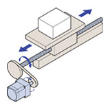
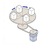
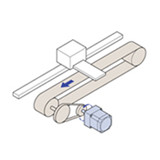
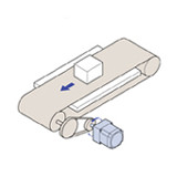
Oriental Motor offers a wide range of motion control products to meet a wide range of applications, select the appropriate application type below.
We're Here to Help
Business Hours - Monday to Friday, 8:30am EST to 5:00pm PST
U.S.A. Customers:
Customer Service - 1-800-418-7903
Tech Support – 1-800-GO-VEXTA (468-3982)
International Customers:
+1-847-871-5931 or
+1-310-715-3303
For Japanese:
1-800-746-6872 or
+1-310-715-3303
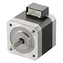
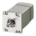
The AZ Series offers closed loop control, substantially reduces heat generation from the motor and by incorporating the newly developed Mechanical Absolute Encoder, absolute-type positioning is available, without battery back-up or external sensors to buy. Requires AZ Series Driver.
- 1.65 in. (42 mm) Frame Size
- Battery-Free, Mechanical Absolute Encoder
- AC Input
- Geared Type Available
- Electromagnetic Brake Type Available
| Items |
 /Asset/azm46ac-img.jpg /Asset/azm46ac-img.jpg AZM46AC 1.65 in. (42mm) Mechanical Absolute Encoder, Closed Loop Stepper Motor Web Price $307.00
|
 /Asset/azm46mc-img.jpg /Asset/azm46mc-img.jpg AZM46MC 1.65 in. (42mm) Mechanical Absolute Encoder, Closed Loop Stepper Motor Web Price $466.00
|
 /Asset/azm46ac-ts_-img.jpg /Asset/azm46ac-ts_-img.jpg AZM46AC-TS3.6 1.65 in. (42mm) Mechanical Absolute Encoder, Closed Loop Stepper Motor Web Price $441.00
|
 /Asset/azm46ac-ts_-img.jpg /Asset/azm46ac-ts_-img.jpg AZM46AC-TS7.2 1.65 in. (42mm) Mechanical Absolute Encoder, Closed Loop Stepper Motor Web Price $441.00
|
 /Asset/azm46ac-ts_-img.jpg /Asset/azm46ac-ts_-img.jpg AZM46AC-TS10 1.65 in. (42mm) Mechanical Absolute Encoder, Closed Loop Stepper Motor Web Price $457.00
|
|||||
| Frame Size | - 1.65 in42 mm | |||||||||
| Motor Length | - 2.76 in.70 mm | - 3.98 in.101 mm | - 3.98 in.101 mm | - 3.98 in.101 mm | - 3.98 in.101 mm | |||||
| Driver Voltage Input Power | - AC | |||||||||
| Speed-Torque Characteristics |
-
 Speed - Torque Characteristics |
-
 Speed - Torque Characteristics |
-
 Speed - Torque Characteristics |
-
 Speed - Torque Characteristics |
-
 Speed - Torque Characteristics |
|||||
|
Holding Torque |
- 42 oz-in0.30 N·m | - 42 oz-in0.30 N·m | - 92 oz-in0.65 N·m | - 170 oz-in1.20 N·m | - 240 oz-in1.70 N·m | |||||
| Shaft/Gear Type | - Round Shaft (No Gearhead) | - Round Shaft (No Gearhead) | - Taper Hobbed Gear | - Taper Hobbed Gear | - Taper Hobbed Gear | |||||
| Gear Ratio (X:1) | - | - | - 3.6 :1 | - 7.2 :1 | - 10 :1 | |||||
| Backlash | - | - | - 45 arc min (0.75°) | - 25 arc min (0.42°) | - 25 arc min (0.42°) | |||||
| Lost Motion | - | |||||||||
| Shaft | - Single | |||||||||
| Electromagnetic Brake | - Not Equipped | - Equipped | - Not Equipped | - Not Equipped | - Not Equipped | |||||
| Permissible Speed Range (r/min) | - | - | - 0 ~ 833 | - 0 ~ 416 | - 0 ~ 300 | |||||
| Rotor Inertia | - 0.30 oz-in²55×10-7 kg·m² | - 0.39 oz-in²71×10-7 kg·m² | - 0.30 oz-in²55×10-7 kg·m² | - 0.30 oz-in²55×10-7 kg·m² | - 0.30 oz-in²55×10-7 kg·m² | |||||
|
RoHS Compliant |
- These products do not contain substances that exceed the regulation values in the RoHS Directive. | |||||||||
|
Safety Standards |
- UL CE | |||||||||
| Permissible Overhung Load | - 0 in. from Shaft End = 7.8 lb0.2 in. from Shaft End = 9.9 lb0.39 in. from Shaft End = 13 lb0.59 in. from Shaft End = 19.1 lb0 mm from Shaft End = 35 N5 mm from Shaft End = 44 N10 mm from Shaft End = 58 N15 mm from Shaft End = 85 N | - 0 in. from Shaft End = 7.8 lb0.2 in. from Shaft End = 9.9 lb0.39 in. from Shaft End = 13 lb0.59 in. from Shaft End = 19.1 lb0 mm from Shaft End = 35 N5 mm from Shaft End = 44 N10 mm from Shaft End = 58 N15 mm from Shaft End = 85 N | - 0 in. from Shaft End = 4.5 lb0.2 in. from Shaft End = 6.7 lb0.39 in. from Shaft End = 9 lb0.59 in. from Shaft End = 11.2 lb0 mm from Shaft End = 20 N5 mm from Shaft End = 30 N10 mm from Shaft End = 40 N15 mm from Shaft End = 50 N | - 0 in. from Shaft End = 4.5 lb0.2 in. from Shaft End = 6.7 lb0.39 in. from Shaft End = 9 lb0.59 in. from Shaft End = 11.2 lb0 mm from Shaft End = 20 N5 mm from Shaft End = 30 N10 mm from Shaft End = 40 N15 mm from Shaft End = 50 N | - 0 in. from Shaft End = 4.5 lb0.2 in. from Shaft End = 6.7 lb0.39 in. from Shaft End = 9 lb0.59 in. from Shaft End = 11.2 lb0 mm from Shaft End = 20 N5 mm from Shaft End = 30 N10 mm from Shaft End = 40 N15 mm from Shaft End = 50 N | |||||
| Permissible Thrust Load | - 0.96 lb4.30 N | - 1.35 lb6 N | - 3.30 lb15 N | - 3.30 lb15 N | - 3.30 lb15 N | |||||
| Permissible Thrust Load | - | |||||||||
|
|
||||||||||

