![]()
Para Inglés o Español:
Para japonés:
Clientes de Mexíco:
Servicio Al Cliente - +001-847-871-5931
Soporte técnico - 01-800-681-5309
Clientes Internacionales:
+1-847-871-5931 o
+1-310-715-3304
Para soporte en productos del catálogo japonés:
1-800-746-6872 o
+1-310-715-3304
El contenido a continuación está en inglés
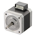
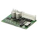
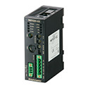
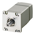
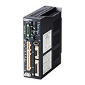
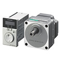
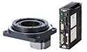
Servo Motor Driver

- Extended Functions available with control module OPX-2A (sold separately) or the data setting software MEXE02 (free download)
Power Input |
- Single-Phase 200-230 VAC / Three-Phase 200-230 VAC |
Motor Output Power |
- 100 W (1/8 HP) 200 W (1/4 HP) 50 W (1/15 HP) |
Voltage and Frequency |
- -15% to +10% 50/60 Hz |
DC Control Power Supply |
- 25 VDC ±10% 0.8 A |
| Rated Input Current1 |
-
2.8 A (Single-Phase 200-230 VAC) 1.6 A (Three-Phase 200-230 VAC) |
Interface |
- Pulse, Analog Speed Command Voltage, Analog Torque Command Voltage |
Maximum Input Pulse Frequency |
-
Line driver output by programmable controller: 500kHz (When pulse duty is 50%) Open collector output by porgrammable controller: 250 kHz (When pulse duty is 50%) |
Protective Function |
-
When the following protective functions are activated, an alarm signal is output and the motor is stopped. Overflow, Overcurrent Protection, Overheat Protection, Overvoltage Protection, Main Power Supply Error, Undervoltage, Motor Overheat Protection, Sensor Error during Operation, Encoder Communication Error, Overload, Overspeed, Position Range Error, Absolute Position Loss, Command Pulse Error, EEPROM Error, Sensor Error during Initialization, Rotor Rotation during Initialization, Encoder EEPROM Error, Motor Combination Error, ABS Not Supported, No Battery, Regeneration Unit Overheat, Electronic Gear Setting Error |
Input Signal |
-
• Photocoupler Input, Input Resistance: 3 kΩ Input Signal Voltage: 4.75 to 26.4 VDC (S-ON, CLR/ALM-RST/P-CK,P-REQ/BRAKE, TL/W-RESET, MO, M1, P-PRESET/M2, FREE) • Photocoupler Input, Input Resistance: 2.7 kΩ Input Voltage: 21.6 to 26.4 VDC (CW+24 V/PLS+24 V, CCW+24 V/DIR+24 V) • Photocoupler Input, Input Resistance 200 Ω Input Voltage: 3 to 5.25 VDC (CW/PLS, CCW/DIR) • Analog Input Set with Internal Potentiometer (VR1, VR2) Analog Input Voltage +10 VDC Input Impedance 15 kΩ Set with External Potentiometer 20 kΩ 1/4 W (V-REF, T-REF, P-REF, P-TREF) |
Output Signal |
-
• Photocoupler and Open Collector Output External use conditions: 30 VDC, 10 mA max. (ALM, WNG/MOVE/MBC, END/VA, READY/ALO/P-OUTR, TLC/VLC/AL1/P-OUTO, ZSG2/NEAR/ZV/AL2/P-OUT1) • Line Driver Output External use condition: Connect a terminating resistor of 100 Ω min. between the line receiver inputs. (ASG, BSG, ZSG1) • Analog Monitor Output Analog Output Voltage ±10 VDC Output Impedance 1 kΩ (V-MON, T-MON, SG) |
Other Functions |
-
Position Control, Speed Control, Torque Control, Tension Control Automatic Tuning, Damping Control Function (7 to 30 Hz), Position Preset Function, Current Position Output Function, Torque Limiting Function Pulse Input Mode (2-Pulse Input, 1-Pulse Input), Analog Monitor Output Function (Speed, Torque), Absolute System Enabled/Disabled Warning Output Function, (Overflow, Overheat, Overvoltage, Main Power Supply, Undervoltage, Battery Undervoltage, Overload, Overspeed, Absolute Position Loss, Electronic Gear Setting Error) |
Extended Functions |
- When using the control module OPX-2A (sold separately) or the data setting software MEXE02 (free download) |
Insulation Resistance |
-
100 MΩ min when measured with a 500 VDC megger between the following locations:
|
Dielectric Voltage |
-
No abnormality is judged with the following application for 1 minute:
|
Ambient Temperature (Driver) |
- 0 ~ +50°C (32 ~ 122°F) (non-freezing) |
Ambient Humidity |
- 85% max. (non-condensing) |
Operating Atmosphere |
- No corrosive gases or dust. The product should not be exposed to water, oil or other liquids. |
Degree of Protection |
- IP20 |
|
|

- 1 Thee values are for operation in the continuous duty region. For operation in the limited duty region, the maximum current is approximately 3 times the value shown.