![]()
Para Inglés o Español:
Para japonés:
Clientes de Mexíco:
Servicio Al Cliente - +001-847-871-5931
Soporte técnico - 01-800-681-5309
Clientes Internacionales:
+1-847-871-5931 o
+1-310-715-3304
Para soporte en productos del catálogo japonés:
1-800-746-6872 o
+1-310-715-3304

El contenido a continuación está en inglés
| Items |
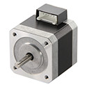
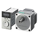
 /Asset/azm66ac-img.jpg /Asset/azm66ac-img.jpg AZM66AC 2.36 in. (60 mm) Mechanical Absolute Encoder, Closed Loop Stepper Motor Web Price $362.00
|
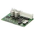
 /Asset/azm66mc-img.jpg /Asset/azm66mc-img.jpg AZM66MC 2.36 in. (60 mm) Mechanical Absolute Encoder, Closed Loop Stepper Motor Web Price $565.00
|
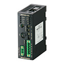
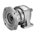
 /Asset/azm69ac-img.jpg /Asset/azm69ac-img.jpg AZM69AC 2.36 in. (60 mm) Mechanical Absolute Encoder, Closed Loop Stepper Motor Web Price $367.00
|
/Asset/azm66mc-img.jpg AZM69MC 2.36 in. (60 mm) Mechanical Absolute Encoder, Closed Loop Stepper Motor Web Price $571.00
|
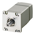
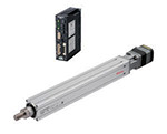
 /Asset/azm66ac-ts_-img.jpg /Asset/azm66ac-ts_-img.jpg AZM66AC-TS3.6 2.36 in. (60 mm) Mechanical Absolute Encoder, Closed Loop Stepper Motor Web Price $519.00
|
|||||
| Frame Size | 2.36 in60 mm | |||||||||
| Motor Length | 2.83 in.72 mm | 4.65 in.118 mm | 3.84 in.97.50 mm | 5.65 in.143.50 mm | 4.53 in.115 mm | |||||
| Driver Voltage Input Power | AC | |||||||||
| Speed-Torque Characteristics |
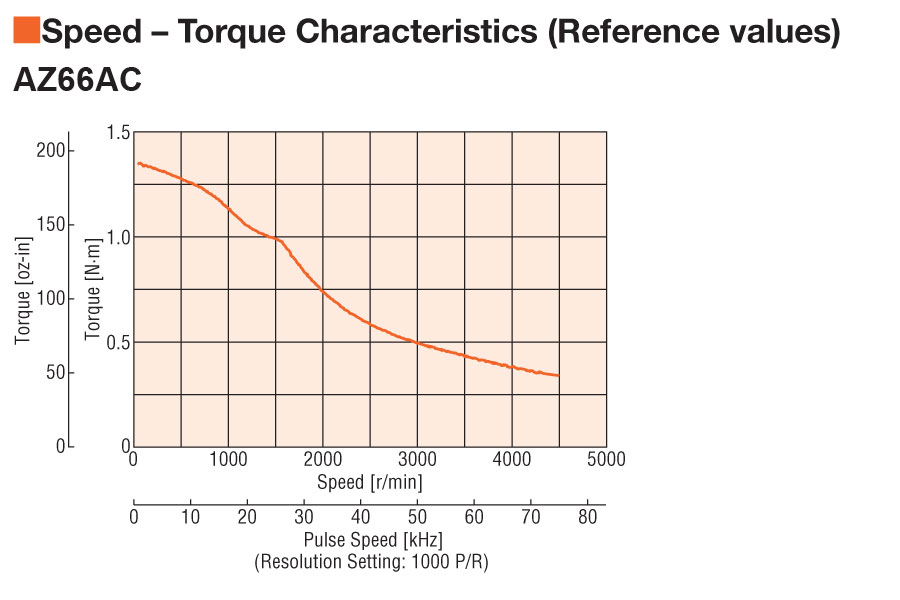 Speed - Torque Characteristics |
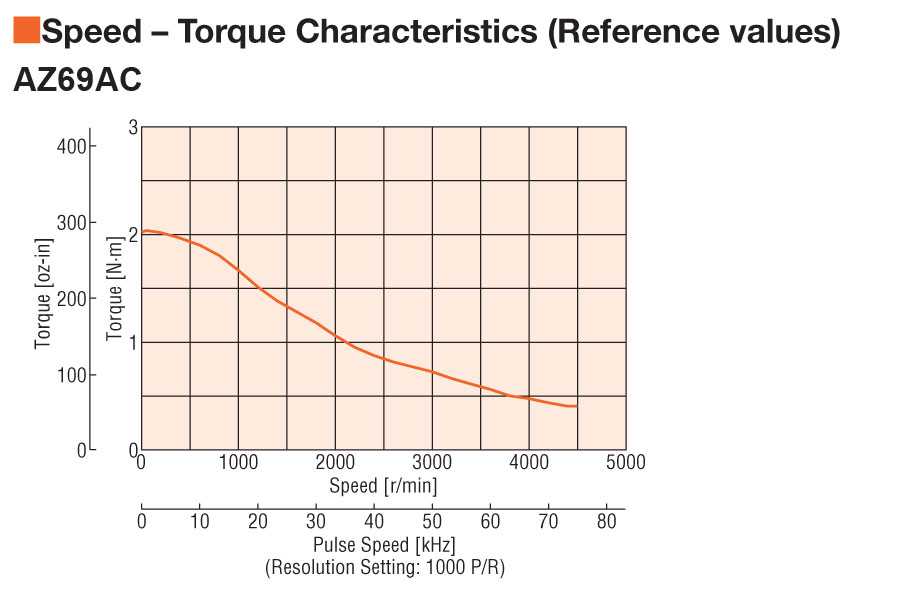 Speed - Torque Characteristics |
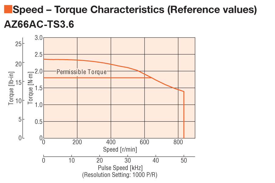 Speed - Torque Characteristics |
|||||
| Holding Torque | 170 oz-in1.20 N·m | 170 oz-in1.20 N·m | 280 oz-in2 N·m | 280 oz-in2 N·m | 255 oz-in1.80 N·m | |||||
| Shaft/Gear Type | Round Shaft (No Gearhead) | Round Shaft (No Gearhead) | Round Shaft (No Gearhead) | Round Shaft (No Gearhead) | Taper Hobbed Gear | |||||
| Gear Ratio (X:1) | 3.6 :1 | |||||||||
| Backlash | 35 arc min (0.59°) | |||||||||
| Lost Motion | ||||||||||
| Shaft | Single | |||||||||
| Electromagnetic Brake | Not Equipped | Equipped | Not Equipped | Equipped | Not Equipped | |||||
| Permissible Speed Range (r/min) | 0 ~ 833 | |||||||||
| Rotor Inertia | 2 oz-in²370×10-7 kg·m² | 2.90 oz-in²530×10-7 kg·m² | 4 oz-in²740×10-7 kg·m² | 4.90 oz-in²900×10-7 kg·m² | 2 oz-in²370×10-7 kg·m² | |||||
| RoHS Compliant | These products do not contain substances that exceed the regulation values in the RoHS Directive. | |||||||||
| Safety Standards | UL CE | |||||||||
| Permissible Overhung Load | 0 in. from Shaft End = 20 lb0.2 in. from Shaft End = 22 lb0.39 in. from Shaft End = 29 lb0.59 in. from Shaft End = 40 lb0.79 in. from Shaft End = 60 lb0 mm from Shaft End = 90 N5 mm from Shaft End = 100 N10 mm from Shaft End = 130 N15 mm from Shaft End = 180 N20 mm from Shaft End = 270 N | 0 in. from Shaft End = 20 lb0.2 in. from Shaft End = 22 lb0.39 in. from Shaft End = 29 lb0.59 in. from Shaft End = 40 lb0.79 in. from Shaft End = 60 lb0 mm from Shaft End = 90 N5 mm from Shaft End = 100 N10 mm from Shaft End = 130 N15 mm from Shaft End = 180 N20 mm from Shaft End = 270 N | 0 in. from Shaft End = 20 lb0.2 in. from Shaft End = 22 lb0.39 in. from Shaft End = 29 lb0.59 in. from Shaft End = 40 lb0.79 in. from Shaft End = 60 lb0 mm from Shaft End = 90 N5 mm from Shaft End = 100 N10 mm from Shaft End = 130 N15 mm from Shaft End = 180 N20 mm from Shaft End = 270 N | 0 in. from Shaft End = 20 lb0.2 in. from Shaft End = 22 lb0.39 in. from Shaft End = 29 lb0.59 in. from Shaft End = 40 lb0.79 in. from Shaft End = 60 lb0 mm from Shaft End = 90 N5 mm from Shaft End = 100 N10 mm from Shaft End = 130 N15 mm from Shaft End = 180 N20 mm from Shaft End = 270 N | 0 in. from Shaft End = 27 lb0.2 in. from Shaft End = 30 lb0.39 in. from Shaft End = 33 lb0.59 in. from Shaft End = 37 lb0.79 in. from Shaft End = 40 lb0 mm from Shaft End = 120 N5 mm from Shaft End = 135 N10 mm from Shaft End = 150 N15 mm from Shaft End = 165 N20 mm from Shaft End = 180 N | |||||
| Permissible Thrust Load | 2 lb8.90 N | 2.80 lb12.70 N | 3.10 lb14 N | 3.90 lb17.60 N | 9 lb40 N | |||||
| Permissible Thrust Load | ||||||||||
|
|
||||||||||